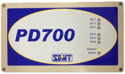
PD700
A complete Partial Discharge (PD) monitoring system for HV Gas Insulated Switchgears (GIS)
Key Features
- Online Measurement
- PD Location
- PD Expert System
- Advanced Data Display
Benefits
- Reliable PD monitoring
- Competitive Cost
- Remote Monitoring
- IEC 61850 Ready
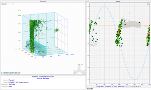
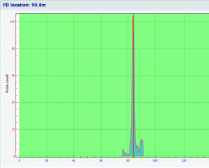
Knowing you have PD (partial discharge) is a worry, knowing where the PD is allows you to make risk assessments. The highly advanced timing system in the PD700 allows the location of the PD to be calculated within the GIS. The PD700 system can provide automated simple results, or advanced screens for experts even down to showing the pulse timing sequences between channels.
The PD700 offers unrivaled features for a cost effective solution. Monitor full HV GIS substations with one simple system. Local units (LAUs) are mounted at convenient location close to the GIS. Simple daisy-chain style connections means fast and simple installation between LAUs and server. Automatically generated warnings for PD within the GIS before failure occurs.
The unique PD Intensity is used to measure the energy in the PD. Advanced analysis developed from experts in the field of GIS and PD signals. The combined results give accurate warnings that minimize the false alarms for the operator. Dedicated hardware allows the location of the PD to be calculated. Knowing where the PD is located is as important as detecting PD. Only with the location information can the true risk be assessed. This built-in feature avoids costly site visits from PD experts to locate the signal.
The location system has the additional benefit of removing the same signal being seen on multiple channels. A common problem of UHF PDM systems is to have many additional signals spread across a number of sensors. This is no longer a problem for the PD700, the operator need only look at one signal from each
PD source.

Installation is simplified by the daisy-chain configuration. 2 fibers and 1 power connection link unit to unit. The PD700 system self calibrates to allow the time of arrival results to be accurate to better than 1 nanosecond. The far end of the daisy-chain can be linked back to the server to provide an alternate data path for security. A star configuration can be used over Ethernet, however, the precision timing between units is only available if the daisy-chain fiber is connected. Standard Ethernet is not suitable for timing between units.
The graphical interface and monitoring system is not limited to the GIS or PD700. Many of the installed monitoring systems from SDMT can be added on to extend the system to monitor other parts of the substation.
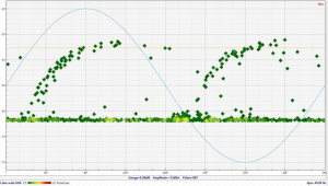
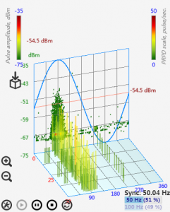
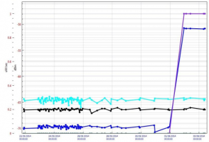
The main software interface is simple enough to be used with minimal training. A full range of trends, patterns and parameters are available for the expert user. Custom real views can be used if available, or any other representation of the GIS. Basic parameters are displayed on the real and schematic views.
| Specifications | |
|---|---|
| Number of PD channels per unit | 6 |
| Maximum number of units | 100+ (600+ HF/UHF channels) |
| UHF PD frequency bandwidth | 300 MHz ... 1.5 GHz |
| UHF PD amplitude range | -75 dBm ... -5 dBm |
| PD location accuracy | <50 cm |
| Communication interfaces | Fiber Ethernet, USB, RS-485 |
| Connectivity output | SCADA, IEC 61850 |
| Input power supply | 90 V ... 260 V, AC (50/60 Hz) or DC |
| Operating temperature range | -20°C to 70°C |
| Relative humidity range | <95% non-condensing |